Overview
5V 8-bit 16 MHz AVR
The Arduino/Genuino Mega 2560 is a microcontroller board based on the ATmega2560. It has 54 digital input/output pins (of which 15 can be used as PWM outputs), 16 analog inputs, 4 UARTs (hardware serial ports), a 16 MHz crystal oscillator, a USB connection, a power jack, an ICSP header, and a reset button. It contains everything needed to support the microcontroller; simply connect it to a computer with a USB cable or power it with a AC-to-DC adapter or battery to get started. The Mega 2560 board is compatible with most shields designed for Arduino/Genuino Uno and the former boards Duemilanove or Diecimila.
The Arduino/Genuino Mega 2560 is an update to the Arduino Mega, which it replaces.
You can find here your board warranty informations.
Getting Started
You can find in the Gett ing Started section all the information you need to configure your board, use the Arduino So ftware (IDE), and start tinker with coding and electronics.
Need Help?
On the Software on the Arduino Forum
On Projects on the Arduino Forum
On the Product itself through our Customer Support
Technical specs
Microcontroller ATmega2560
Operating Voltage 5V
Input Voltage (recommended) 7-12V
Input Voltage (limit) 6-20V
Digital I/O Pins 54 (of which 15 provide PWM output)
Analog Input Pins 16
DC Current per I/O Pin 20 mA
DC Current for 3.3V Pin 50 mA
Flash Memory 256 KB of which 8 KB used by bootloader
SRAM 8 KB
EEPROM 4 KB
Clock Speed 16 MHz
Length 101.52 mm
Width 53.3 mm
Weight 37 g
Documentation
OSH: Schematics, Reference Design, Board size
Arduino / Genuino Mega 2560 is open-source hardware! You can build your own board using the follwing files:
EAGLEEAGLE FILES
IN .ZIP PDFSCHEMATICS
IN .PDF DXFBOARD SIZE
IN .DXF
Programming
The Arduino/Genuino 2560 Mega board can be programmed with the Arduino Software (IDE). For details, see the reference and tutorials.
The ATmega2560 on the Arduino/Genuino Mega 2560 comes preprogrammed with a bootloader that allows you to upload new code to it without the use of an external hardware programmer. It communicates using the original STK500 protocol (reference, C header files).
You can also bypass the bootloader and program the microcontroller through the ICSP (In-Circuit Serial Programming) header using Arduino ISP or similar; see these instructions for details.
The ATmega16U2 (or 8U2 in the rev1 and rev2 boards) firmware source code is available in the Arduino repository. The ATmega16U2/8U2 is loaded with a DFU bootloader, which can be activated by:
On Rev1 boards: connecting the solder jumper on the back of the board (near the map of Italy) and then resetting the 8U2.
On Rev2 or later boards: there is a resistor that pulling the 8U2/16U2 HWB line to ground, making it easier to put into DFU mode. You can then use Atmel's FLIP software (Windows) or the DFU programmer (Mac OS X and Linux) to load a new firmware. Or you can use the ISP header with an external programmer (overwriting the DFU bootloader). See this user-contributed tutorial for more information.
Warnings
The Arduino/Genuino Mega 2560 has a resettable polyfuse that protects your computer's USB ports from shorts and overcurrent. Although most computers provide their own internal protection, the fuse provides an extra layer of protection. If more than 500 mA is applied to the USB port, the fuse will automatically break the connection until the short or overload is removed.
Power
The Arduino/Genuino Mega 2560 can be powered via the USB connection or with an external power supply. The power source is selected automatically.
External (non-USB) power can come either from an AC-to-DC adapter (wall-wart) or battery. The adapter can be connected by plugging a 2.1mm center-positive plug into the board's power jack. Leads from a battery can be inserted in the GND and Vin pin headers of the POWER connector.
The board can operate on an external supply of 6 to 20 volts. If supplied with less than 7V, however, the 5V pin may supply less than five volts and the board may become unstable. If using more than 12V, the voltage regulator may overheat and damage the board. The recommended range is 7 to 12 volts.
The power pins are as follows:
Vin. The input voltage to the board when it's using an external power source (as opposed to 5 volts from the USB connection or other regulated power source). You can supply voltage through this pin, or, if supplying voltage via the power jack, access it through this pin.
5V. This pin outputs a regulated 5V from the regulator on the board. The board can be supplied with power either from the DC power jack (7 - 12V), the USB connector (5V), or the VIN pin of the board (7-12V). Supplying voltage via the 5V or 3.3V pins bypasses the regulator, and can damage your board. We don't advise it.
3V3. A 3.3 volt supply generated by the on-board regulator. Maximum current draw is 50 mA.
GND. Ground pins.
IOREF. This pin on the board provides the voltage reference with which the microcontroller operates. A properly configured shield can read the IOREF pin voltage and select the appropriate power source or enable voltage translators on the outputs for working with the 5V or 3.3V.
Memory
The ATmega2560 has 256 KB of flash memory for storing code (of which 8 KB is used for the bootloader), 8 KB of SRAM and 4 KB of EEPROM (which can be read and written with the EEPROM library).
Input and Output
See the mapping between Arduino pins and Atmega2560 ports:
PIN_MAPPINGPIN MAPPING
Atmega2560
Each of the 54 digital pins on the Mega can be used as an input or output, using pinMode(), digitalWrite(), and digitalRead() functions. They operate at 5 volts. Each pin can provide or receive 20 mA as recommended operating condition and has an internal pull-up resistor (disconnected by default) of 20-50 k ohm. A maximum of 40mA is the value that must not be exceeded to avoid permanent damage to the microcontroller.
In addition, some pins have specialized functions:
Serial: 0 (RX) and 1 (TX); Serial 1: 19 (RX) and 18 (TX); Serial 2: 17 (RX) and 16 (TX); Serial 3: 15 (RX) and 14 (TX). Used to receive (RX) and transmit (TX) TTL serial data. Pins 0 and 1 are also connected to the corresponding pins of the ATmega16U2 USB-to-TTL Serial chip.
External Interrupts: 2 (interrupt 0), 3 (interrupt 1), 18 (interrupt 5), 19 (interrupt 4), 20 (interrupt 3), and 21 (interrupt 2). These pins can be configured to trigger an interrupt on a low level, a rising or falling edge, or a change in level. See the attachInterrupt() function for details.
PWM: 2 to 13 and 44 to 46. Provide 8-bit PWM output with the analogWrite() function.
SPI: 50 (MISO), 51 (MOSI), 52 (SCK), 53 (SS). These pins support SPI communication using the SPI library. The SPI pins are also broken out on the ICSP header, which is physically compatible with the Arduino /Genuino Uno and the old Duemilanove and Diecimila Arduino boards.
LED: 13. There is a built-in LED connected to digital pin 13. When the pin is HIGH value, the LED is on, when the pin is LOW, it's off.
TWI: 20 (SDA) and 21 (SCL). Support TWI communication using the Wire library. Note that these pins are not in the same location as the TWI pins on the old Duemilanove or Diecimila Arduino boards.
See also the mapping Arduino Mega 2560 PIN diagram.
Arduino/Genuino Mega 2560 has 16 analog inputs, each of which provide 10 bits of resolution (i.e. 1024 different values). By default they measure from ground to 5 volts, though is it possible to change the upper end of their range using the AREF pin and analogReference() function.
There are a couple of other pins on the board:
AREF. Reference voltage for the analog inputs. Used with analogReference().
Reset. Bring this line LOW to reset the microcontroller. Typically used to add a reset button to shields which block the one on the board.
Communication
The Arduino/Genuino Mega 2560 board has a number of facilities for communicating with a computer, another board, or other microcontrollers. The ATmega2560 provides four hardware UARTs for TTL (5V) serial communication. An ATmega16U2 (ATmega 8U2 on the revision 1 and revision 2 boards) on the board channels one of these over USB and provides a virtual com port to software on the computer (Windows machines will need a .inf file, but OSX and Linux machines will recognize the board as a COM port automatically. The Arduino Software (IDE) includes a serial monitor which allows simple textual data to be sent to and from the board. The RX and TX LEDs on the board will flash when data is being transmitted via the ATmega8U2/ATmega16U2 chip and USB connection to the computer (but not for serial communication on pins 0 and 1).
A SoftwareSerial library allows for serial communication on any of the Mega 2560's digital pins.
The Arduino/Genuino Mega 2560 also supports TWI and SPI communication. The Arduino Software (IDE) includes a Wire library to simplify use of the TWI bus; see the documentation for details. For SPI communication, use the SPI library.
Physical Characteristics and Shield Compatibility
The maximum length and width of the Arduino/Genuino Mega 2560 PCB are 4 and 2.1 inches respectively, with the USB connector and power jack extending beyond the former dimension. Three screw holes allow the board to be attached to a surface or case. Note that the distance between digital pins 7 and 8 is 160 mil (0.16"), not an even multiple of the 100 mil spacing of the other pins.
Arduino/Genuino Mega 2560 is designed to be compatible with most shields designed for Arduino/Genuino Uno and the older Diecimila or Duemilanove Arduino boards. Digital pins 0 to 13 (and the adjacent AREF and GND pins), analog inputs 0 to 5, the power header, and ICSP header are all in equivalent locations. Furthermore, the main UART (serial port) is located on the same pins (0 and 1), as are external interrupts 0 and 1 (pins 2 and 3 respectively). SPI is available through the ICSP header on both the Arduino/Genuino Mega 2560 and Duemilanove / Diecimila boards. Please note that I2C is not located on the same pins on the Mega 2560 board (20 and 21) as the Duemilanove / Diecimila boards (analog inputs 4 and 5).
Automatic (Soft ware) Reset
Rather then requiring a physical press of the reset button before an upload, the Arduino/Genuino Mega 2560 is designed in a way that allows it to be reset by software running on a connected computer. One of the hardware flow control lines (DTR) of the ATmega8U2 is connected to the reset line of the ATmega2560 via a 100 nanofarad capacitor. When this line is asserted (taken low), the reset line drops long enough to reset the chip. The Arduino Software (IDE) uses this capability to allow you to upload code by simply pressing the upload button in the Arduino environment. This means that the bootloader can have a shorter timeout, as the lowering of DTR can be well-coordinated with the start of the upload.
This setup has other implications. When the Arduino/Genuino Mega 2560 board is connected to either a computer running Mac OS X or Linux, it resets each time a connection is made to it from software (via USB). For the following half-second or so, the bootloader is running on the ATMega2560. While it is programmed to ignore malformed data (i.e. anything besides an upload of new code), it will intercept the first few bytes of data sent to the board after a connection is opened. If a sketch running on the board receives one-time configuration or other data when it first starts, make sure that the software with which it communicates waits a second after opening the connection and before sending this data.
The Arduino/Genuino Mega 2560 board contains a trace that can be cut to disable the auto-reset. The pads on either side of the trace can be soldered together to re-enable it. It's labeled "RESET-EN". You may also be able to disable the auto-reset by connecting a 110 ohm resistor from 5V to the reset line; see this forum thread for details.
Revisions
Arduino/Genuino Mega 2560 does not use the FTDI USB-to-serial driver chip used in past designs. Instead, it features the ATmega16U2 (ATmega8U2 in the revision 1 and revision 2 Arduino boards) programmed as a USB-to-serial converter.
Revision 2 of the Mega 2560 board has a resistor pulling the 8U2 HWB line to ground, making it easier to put into DFU mode.
Revision 3 of the Arduino board and the current Genuino Mega 2560 have the following improved features:
1.0 pinout: SDA and SCL pins - near to the AREF pin - and two other new pins placed near to the RESET pin, the IOREF that allow the shields to adapt to the voltage provided from the board. In future, shields will be compatible both with the board that use the AVR, which operate with 5V and with the board that uses ATSAM3X8E, that operate with 3.3V. The second one is a not connected pin, that is reserved for future purposes.
Stronger RESET circuit.
Atmega 16U2 replace the 8U2.
2015年9月10日星期四
Arduino Uno
Arduino Uno
The Arduino Uno is the current original form factor board. It is based on the ATmega328. The Uno has 14 digital I/O pins and 6 analog inputs. There are 6 digital pins that may be used for PWM output. A complete development system of sorts may be made with the Arduino Uno, the Arduino IDE software, and a USB connected to your personal computer.
The Uno is the first Arduino to use the ATmega8U2 MCU as a USB controller, rather than the FTDI USB to Serial chip. The original Uno was superceded by the Arduino Uno R2, which was a bugfix release that added a pulldown on the HWB pin on the ATmega8U2 to make it easier to reprogram it using DFU mode.
The current version is the Arduino Uno R3, which replaces the ATmega8U2 with the ATmega16U2. It has a stronger reset circuit, and an enhanced pinout that includes SDA and SCL from the I2C bus, and IOREF, a new pin that allows shields to detect the I/O voltage of the Arduino and adapt. Very few shields do yet. You can tell an R3 by the location of the reset switch by the USB connector, and the 10-pin shield header nearby.
A drawback of the Uno R3 is the location of the ICSP connector for the 8U2 or 16U2 USB controller. It is situated such that you have to trim the key on the programming connector in order to fit it on the pins. Otherwise, it hits the 10-pin shield header and prevents the connector from seating. We had a similar problem on the ICSP connector for the ATmega328 - the side of the programmer's connector hits the IC socket. The problem is not as pronounced as the ICSP on the U2.
2015年9月6日星期日
A LOW-COST ROBOTIC HAND (TUTORIAL) MIRRORING YOUR OWN FINGERS
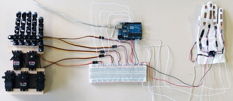
Marco Pucci shared on our Facebook Page a link to the tutorial he made for a low-cost Robotic Hand able to mirror the movement of our own hand. He created it in the laboratory of new technology of Accademia di Belle Arti di Brera (“Academy of fine arts of Brera”), a state-run public academy in Milan, Italy.
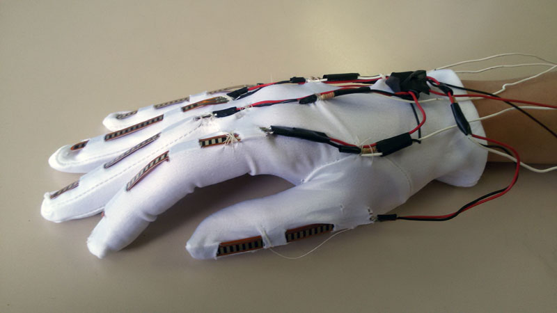
The hand works with flex sensors attached to the glove’s fingers, they are analysed by an Arduino which then moves servo motors connected to threads attached to the robotic hand.
SEND IN THE CLONES
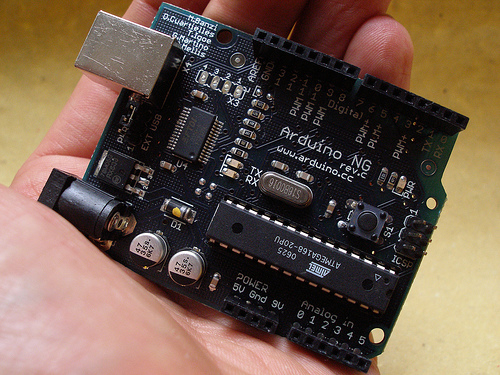
When we came up with Arduino, one of the things we decided very early on was that we wanted to release the hardware design files so that people could make their own versions or just make an exact copy if they couldn’t find boards where they lived.
I think we contributed to popularize the concept of open source hardware and we can see it from the huge amount of variations of Arduino-compatible devices being released every day.
After the platform started to become popular we had the issue of figuring out a business model to sustain our work and keep innovating the project. But we also realized we needed a way for people to be guaranteed that
they were buying a quality product that would replace any defective item, should problems arise
they were contributing to a community that would bring forward open-source values and knowledge sharing
We decided that the best way was to register the trademark of the Arduino lettering and to create a logo that would make it easier to identify products sanctioned by us.
A few years later the situation is clearly complex with so many companies identifying something as an Arduino even if the only thing they have in common with us is the board pinout. It’s time we clarify what in our mind is an Arduino, what are the different variations of Arduino around and how they relate to our project.
We classified them as Clones, Derivatives, Compatibles and Counterfeits. But let’s start with explaining what is an official board.
- Official Boards
An Arduino is a board which
it’s directly supported by the official Arduino IDE
it follows the Arduino layout we have standardised
it’s properly documented on our website
it’s properly licensed to bear the Arduino name and logo
it’s made by authorized manufacturers
The authorized manufacturers pay a small royalty to Arduino to keep the project going (pay for the servers, the people who develop the software, design the hardware, write documentation and provide support, etc.). We sign contracts with them and all the authorised distributors that make sure they will replace any defective board should the customer receive a product they feel is not working properly.
Although the percentage is incredibly small (less than 1%) it’s still important to know that somebody will take care of any issue. Through this system we have enabled people to have access to cheap hardware that is properly supported and the community can build upon.
These are the only boards that can legitimately use the Arduino name.
Current official manufacturers are SmartProjects in Italy, Sparkfun in the USA and DogHunter in Taiwan/China. These are the only manufacturers that are allowed to use the Arduino logo on their boards.
- Clones
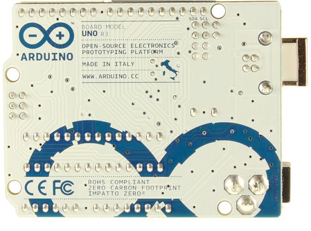
A market developed for products we call Clones which are exact (or almost exact) replicas of Arduino boards with a different branding , i.e. they are usually named with some variation of Ardu-something or something-duino. These products are released according to trademark laws (unless they copy almost exactly our graphics which is not open-source) and have a place in the market.
Customers who want to support the Arduino project should be aware that these products do not give back anything financially and very rarely in term of help on software or documentation.
- Derivatives
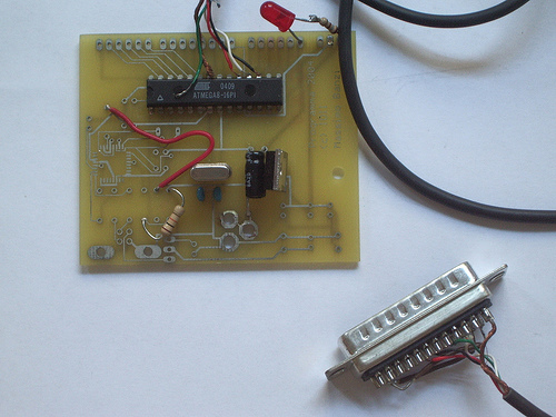
A more interesting segment for us is what we call Derivatives. These are products that are derived from the Arduino hardware design but they innovate either by providing a different layout and features often to better serve a specific market. These are the products that have also helped Arduino become so ubiquitous.
There are many examples but I will mention only a couple:
Teensy by PJRC – Paul has contributed a lot of code, bug reports, pull requests and to the discourse in general.
Flora by Adafruit – Limor has contributed over 100 libraries and countless tutorials about Arduino becoming one of the most important members of the Arduino ecosystem.
- Arduino-compatibles
There is also a hazy cloud of products that call themselves “Arduino-compatible” but their actual compatibility is sometimes really marginal.
We go from products that have a semi-compatible port of the Arduino API but use very different processors, to boards that call themselves an “Arduino” just because they have a couple of connectors mechanically compatible with Arduino.
This, for example, is very common on Kickstarter where a number of projects try to get traction by using (sometimes obsessively) the Arduino keyword throughout the project description. Normally we’re pretty relaxed about these unless they are really shameless, then we email them and sometimes they realize they have gone too far.

- Counterfeits
Finally there is a category of products that are really detrimental to the wholeopen-source hardware movement, we call these “counterfeits”.
These are boards that clone the official board including the Arduino branding (logo and board graphics). Since the Arduino graphics is trademarked and we don’t release any of the files, whoever uses our graphics and logo makes a deliberate act of Trademark infringement. These products not only trick people into thinking they are buying an official Arduino (therefore supporting the Arduino project) but they also provide no support. We’ve had many reports of people buying these products and finding out they are damaged but unfortunately for them the manufacturer is nowhere to be found to provide a replacement.
The most common place where counterfeits can be found is usually on auction sites. Special mention is needed for Amazon.com because of the way the website works: they pool together all the suppliers of a certain product. When the customer buys an Arduino they might get a counterfeit depending from which stock they used. From our side it’s hard to stop them because if we report a counterfeit Arduino on their platform, they will “kick out” all the suppliers including the legitimate ones. We’re still trying to find ways to communicate with Amazon but it’s not easy.
In any case you can read this page explaining how to spot a counterfeit Arduino.
- We love open-source
We believe firmly in open source hardware and we have always systematically released any hardware design and the software needed to reproduce our products. We think this advances the whole community and provides a platform for shared innovation where the advantages are more than the drawbacks, but we also think that Trademark violations are like identity theft: the same way each one of us wants to have the right to own their name we believe we have the right to decide whoever gets to be called Arduino, everything else is right there on Github for anybody to build upon.

DIY LESS-EXPENSIVE THERMAL IMAGING CAMERA
A thermal imaging camera is used for the purpose of energy auditing for homes and offices. Typically these require equipments such as FLIR B60 which are worth $5000 to $8000. This article by David Schneider however talks about a cheap DIY camera. Inspired by the award winning design using Arduino by two two 18-year-old students, Max Ritter and Mark Kohl, from Mindelheim, Germany.
The Schneider version of the thermocam, however, uses a slightly different partlist for the sake of robustness.
The parts used were:
Melexis’s MLX90614?DCI ($52), Arduino microcontroller($30), powder-coated metal enclosure for Arduino($30), Hitec HS425BB x 2 servos($13×2), DDT500H for pan-tilt mechanism($25), plastic mount for servos($5), COM-08654 Laser module with digital controller($19)
here:http://rbacc.com
The applications were numerous:
– Checking around the home for weather-stripping faults. Even minor gaps were shown more clearly.
– Scanning people and imitating Kirilian photography to picture the actual energy that people emit.
For a more step-by-step on how to build, head here.
Happy building!
HOW TO CONTROL ARDUINO BOARD USING AN ANDROID PHONE
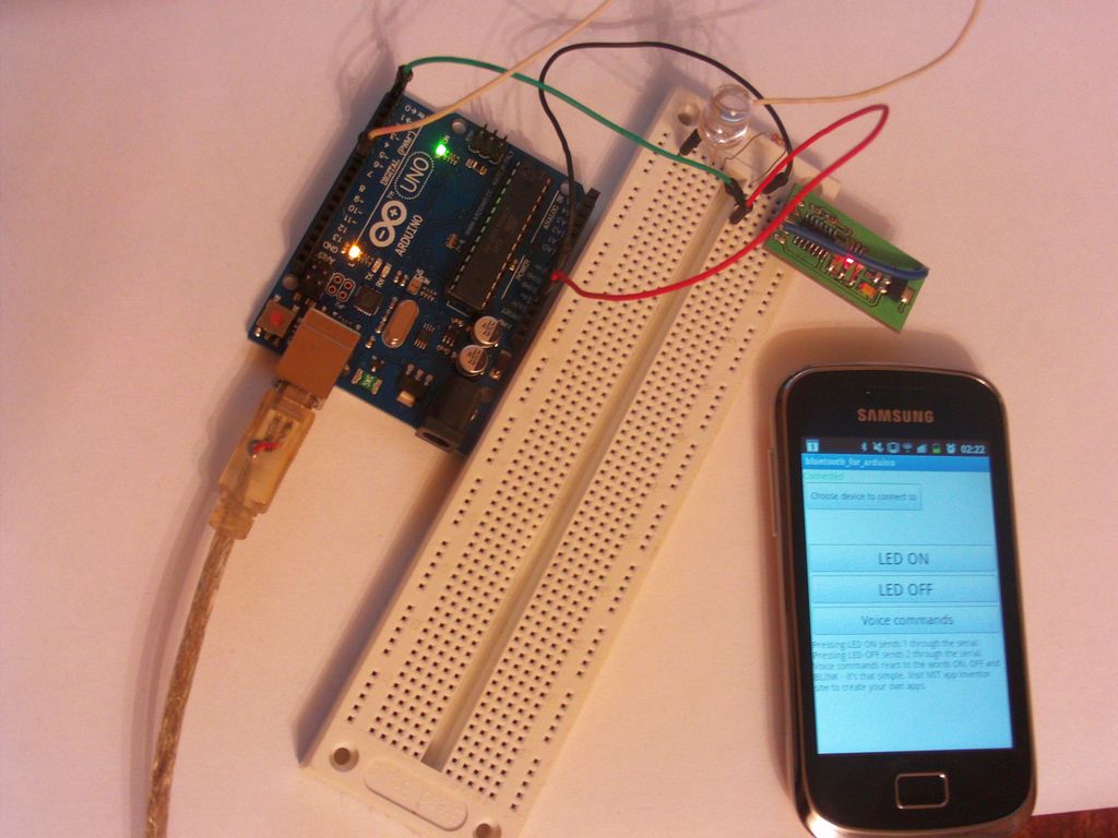
Kerimil, user on Arduino Forum, submitted us his project which focuses on establishing communication between an Arduino board and an android mobile using bluetooth:
The idea is to gain access to hardware on Android devices (accelerometers, gyro, wifi connectivity, gps, GPRS, touchscreen, text to speech and speech to text) and/or use it to relay data to the internet. MIT’s app inventor was used to write a custom app in this example. The code can be easily modified to create your own apps.
You can watch his video below and read the complete tutorial on this page.
RFID Master Kit with Motor Servo , LCD , Various Sensors for Arduino IDE AVR MCU Learner
- (1) It includes 1 RFID-RC522 Module (RFID reader) + 1 RFID Proximity ID Round Tag + 1 RFID Proximity ID Card Tag
- (2) With this kit , you can use it to communicate with arduino board . we will provide the connection diagram and the sample code for you to use with this kit, so the process would become very easier for you to get familiar with this kit.
- (3) So you can start your RFID project as soon as you get this kit , such as use the RFID to open the door etc...and we hope you can also be very creative to use this kit for many awesome ideas !
- (4) Unlike other sellers , we are professional and provide all the tools necessary . other seller might just sell you the hardware, then leave you alone, so you have to spend a lot of time to figure out how to get it to work
- (5) After you purchase , just send an email to us with title "require Arduino pdf files for starters " , then we will show you how to access these PDF documents . so you can save a lot of time searching for these!
DIY Learning Boards Module Kit (Works with Official Arduino Boards)
Our development board using the version of the controller is Funduino UNO, which is the official improved version fully compatible with the official UNO R3; External switching power conversion of the DC-DC converter, used to improve the effectiveness; Improved digital and analog interface, designed with +5V and GND interface; 3.3~5V voltage can be switched; Ideal for new starter of DIY lovers.
Quantity: 1Piece
Color: Multicolored
Material: FR4
Packing List:
1 x UNO control board
1 x Fixed board
1 x LED light
1 x Resistor
1 x Jumper cable (10cm)
1 x Jumper cable (20cm)
1 x DuPont line (20cm)
1 x USB cable (139cm)
1 x Small breadboard
1 x 400 holes breadboard
1 x Battery box (6 x AA, 15cm-cable)
4 x Button switches
1 x RGB LED light
3 x Photoresistors
1 x Flame sensor
2 x Buzzers
1 x Temperature sensor
2 x Tilt switches
1 x IR receiver
1 x Adjustable resistor
1 x 74HC595
1 x Remote controller
1 x 1-digit seven-segment display
1 x 4-digit seven-segment display
1 x 8x8 dot matrix
1 x 9g servo
1 x 1602 screen
1 x Stepper motor
1 x Motor driver board
1 x Stepper
1 x Temperature humidity module
1 x Clock module
订阅:
评论 (Atom)